Parallel circuit is one type of circuit or arrangement of electrical components that are connected in parallel.
The parallel circuit formula is Voltage V= V1=V2=V3, resistance 1/R =1/R1 +1/R2 + 1/R3 and current flowing I = I1 +I2 + I3.
In this modern era, electricity is a very important requirement for life. In fact, almost all human activities require a power source so that it is as if electricity is a cog in everyday life.
However, many people still do not understand electricity, especially the basics of electricity such as series and parallel circuits.
Knowledge of parallel series circuits is something that is commonly used by everyone. An example of its application is when someone wants to install a light installation in his house. Therefore, in this article, we will discuss series and parallel circuits starting from the differences, advantages and disadvantages along with examples of both.
preliminary
Before we dive deeper into series and parallel circuits, we need to know the basics first.
An electrical circuit is a collection of several electrical components that are connected and attached to a voltage. Here are some electrical components along with symbols that are often used in circuits:

There is also a symbol regarding another parameter called electric current. Usually, electric current is indicated by the direction of the arrow on the circuit and the symbol “I”

Difference between Series and Parallel Circuits
As we know, series and parallel circuits have significant differences. Some of these differences include:
Differences in Circuit Arrangement
What we can clearly see from the difference between the two circuits is the arrangement of the components installed. The arrangement can be seen from the branching of the cable or the placement of its components. For more details, here is the description in detail:
Series Circuit

“The series circuit has a simple arrangement so that the series arrangement does not have cable branches between the load or the installed voltage source.”
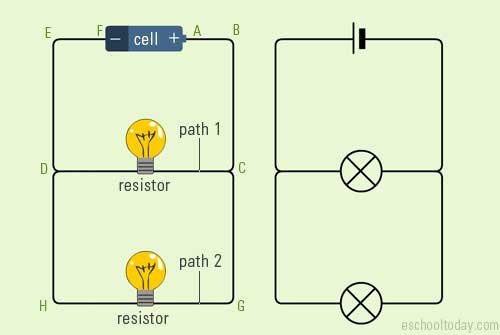
Parallel circuit

“In parallel circuits, there are complex arrangements and there are branching of cables between loads or installed voltages.”
Circuit Component Difference
Apart from the obvious differences in arrangement, we can distinguish series and parallel circuits from the components used. Although the amount of load or resistance can be adjusted, there are differences in the components, including:
Series Circuit
In a series circuit, the components are simpler consisting of a voltage source, cable and load. Although sometimes a series circuit uses a switch, a series circuit only requires one switch.
Parallel circuit
In parallel circuits, the components used tend to be more. An example is the cable that is used in parallel circuits is longer because parallel circuits have branches. In addition, parallel circuits usually use one switch for one load only.
Differences in Physics Formulas and Parameters
In addition to things that are clearly visible, there are other parameters that affect the series and parallel circuits, namely the electric voltage “V” and the electric current “I”. Of course to find these two parameters have different ways for series circuits and parallel circuits. Here’s how to calculate voltage and electric current in series and parallel circuits:
Strong Electric Current

Electric current is a quantity that states every electric charge that flows in a component. In series and parallel circuits, the electric current has a different calculation for each component.
Series Circuit
“The electric current in a series circuit has the same amount of electric current flowing through each resistance. This makes one point on the series circuit equal to another point.”

Parallel circuit
“In a parallel circuit, the sum of the strong currents flowing out of the junctions will be equal to the sum of the strong currents entering the junctions.”

Electrical voltage

In an electric circuit, voltage is the amount of potential energy in an electric field and has units of volts. Electrical voltage in series and parallel circuits have different calculations.
Series Circuit

“In a series circuit, the electric voltage is not as strong as the current, but the voltage that is installed is equal to the voltages on the components.”
Parallel circuit

“Unlike the case with a series circuit, the voltage applied to all circuits will always be the same value in parallel circuits.”
Electrical resistance
In addition to voltage and current sources, there is one more parameter that is commonly owned by each component, namely resistance or load. On the total resistance of each circuit has a different way of addition including:
Series Circuit

“Every resistance that is connected in series in the circuit will add up to each other. So, the total resistance installed is the total resistance of each component.”
Parallel circuit

“While in a parallel circuit all the voltages on the components will be the same value. Therefore the total resistance installed in the parallel circuit as described in the picture above.
Thus the article about series circuits and parallel circuits, hopefully it can be useful for you.