Tag: electronic

  • Electrical Grounding: Functions, Types, How to Install

    Electrical Grounding: Functions, Types, How to Install

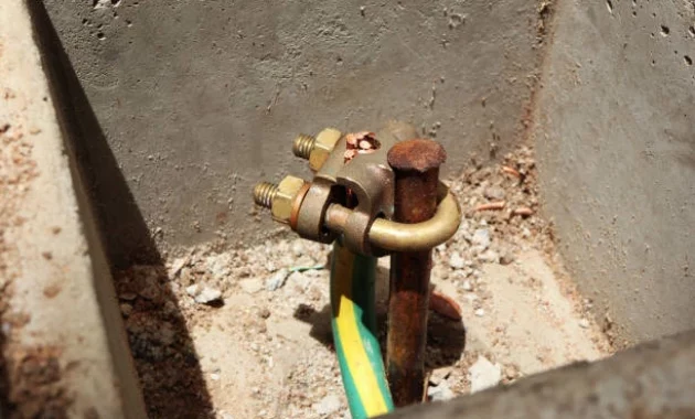
    As we know, this ground is also known as grounding. Where this grounding or grounding is a complementary system that is in every electrical installation. Its own function is as a grounding system.

    In addition, the installation of grounding is also useful to provide protection for home electrical installations from various disturbances and hazards. How, interested to know more about Arde?

    In this article, we will thoroughly discuss what is a grounding or grounding system. Starting from the understanding, function, how it works, symbols, to how to install and how to make a simple ground. We will also examine whether grounding can save electricity.

    Definition of Electrical Grounding

    Definition of Electrical Grounding

    When viewed from its function, it can be said that grounding or what is also known as grounding is a grounding system in the form of a separate cable line that does not connect with other electrical wiring installations installed in home electrical installations to the ground point (earth) .

    So this system was created with the aim of eliminating the potential difference that occurs in the electrical circuit . In addition, at the same time aims to release the excess electric charge that arises.

    With the installation of grounding, when there is an excess load on the electrical installation, the charge will automatically flow into the ground.

    Because the soil has a very large mass and volume, if there are disturbances or problems related to electric charge, it will be quickly neutralized. It is for this purpose that a grounding or grounding system is installed.

    Electrical Grounding / Grounding Function

    Judging from its function, of course this Ground or Grounding needs to be installed in every electrical installation, right? Whether it’s for personal needs such as home areas or industrial areas such as factories, of course it requires the presence of Ground as security.

    The function of grounding is as a form of protection. By installing grounding, electrical installations can avoid the following risks:

    • Grounding serves to prevent large electrical leakage. For example, in the event of an electric short circuit, insulation leakage, and avoiding people from being exposed to electric shocks.
    • Prevents in the event of an induction in the flow voltage.
    • Serves as a protector from the threat of static electricity. Especially static electricity that has a voltage with a very high scale such as a lightning strike.
    • Grounding also serves as a reference for measuring the electric current in the installation.
    • Grounding can also prevent damage caused by voltage leakage.
    • Ground also serves to neutralize noise caused by several factors. Among them due to the quality of components that are far from standard or power quality that is not good.

    How Electric Ground Works

    If observed, the ground installation area is generally deliberately placed close to the kWh meter. So from the kWh meter, the neutral and ground cables are combined together with the phase cable. Then this cable will be connected to the entire network and also the socket.

    From this socket, the grounding will be connected and connected to various electrical equipment . For example, home electrical appliances such as refrigerators, TVs, radios, computers and so on.

    Grounding symbol

    In general, grounding or ground is denoted by certain symbols. This electrical installation symbol is used when you want to draw an electronic circuit .

    Let’s take a look at some of the most common Ground symbols below. Use the following symbols to explain what the meaning of Grounding is each.

    Grounding symbol

    Various Grounding Systems

    When making electrical installations, of course the security system is the most important thing to pay attention to. Therefore, carrying out a grounding or grounding system is important to do.

    Before discussing further about how to install a grounding cable, of course we need to know the various types. The following is a discussion of various grounding systems that you need to know.

    1. Safety Grounding

    Safety grounding is one system that is often used in grounding installations. Safety grounding is used with the aim of neutralizing the impact of dangerous electric currents.

    For example, if there is a voltage and electric current that goes up or down. Whether it’s caused by an electromagnetic wave whose source of emission comes from a flash of lightning or comes from various other reasons.

    To overcome this, the installation of safety grounding can be an option. Because of this, safety grounding systems are often applied to various electrical lines. It is easy to say that grounding is one of the lightning protection systems.

    2. RF Grounding

    RF grounding is a grounding system whose designation is generally used in communication devices. One example is like radio. As for the process of installing RF grounding , it is mostly applied to devices with large needs.

    The purpose of the installation of this system is to reduce the impact of radiation. Especially to ward off the risk of radiation. As we know, this radiation can arise from the emission of radio communication waves.

    Wire Color For Ground

    Wire Color For Ground

    Before you install a grounding system, of course you also need to know the standard size of the home electrical installation cable. Because this cable is the main component needed to make ground or grounding.

    The wire for grounding is usually green or yellow with a green stripe. Cables with yellow green are generally used for conductors.

    For example, its use for various types of conductors. For example, such as earthing conductors and protective conductors. In addition, this yellow green wire is also used to connect equipotential bonds to the ground.

    Cable Size For Ground

    The ground wire for the grounding system is done by planting a pipe in the ground. Where this pipe will be installed on the terminal part of the socket.

    How to install the grounding on the socket must meet the applicable size standards so that its function can be maximized.

    What you need to know, too, is that the installation method will affect the level of security and also the quality of the ground.

    Therefore, the size and specifications of the cable are also points that should not be ruled out if you want to install grounding at home, right?

    The size of the house electrical cable for grounding can later be adjusted to the standards that have been set. The following is the standard size of the power cord for installing grounding in areas of the house that need attention.

    • The use of wires for grounding generally uses yellow-green wires.
    • Minimum grounding cable diameter using a 50 mm cross-section. But when using a cable with a larger diameter is also allowed.
    • Especially for grounding or grounding in a location that is quite sensitive, try using the HVSC (High Voltage Single Core) cable.
    • For outdoor installations, grounding can use a 50 mm NYA type cable.

    How to Install a Good and Standardized Ground

    how to install the correct ground

    The size of the power cord and its strength do have different specifications. The larger the diameter used for grounding, the better the flow of electric current in the circuit.

    With a good flow of electric current, it will not cause a greater burden. In addition, the waste of electricity can also be avoided. So, if someone asks whether grounding can save electricity?

    So the answer is yes. Logically, this grounding or grounding will make the flow of electricity in each circuit better than before. How, of course interesting if you can save electricity, right? In addition, the security of the installation is also more guaranteed with this Grounding.

    Let’s just look at how to install a good grounding cable and of course according to the standards below:

    1. Installing the Grounding Rod

    Installing a grounding or grounding rod is an important step that should not be missed. The more ground rods installed, the better for the installation.

    What are the requirements for installing a grounding rod? Here are the steps that need to be done.

    • Ground rods should be planted with more than one number. Also, make sure to be at least 5 meters apart from each other.
    • Ground rods should be installed more than one and arranged in parallel.
    • Ground rods should be avoided from sandy or rocky soil types because they are poor media.
    • To maximize the grounding system, stick rods should be planted at a distance not too far from the house.

    2. Material Selection For Ground

    To install a good grounding, the material used is also very important to note.

    What are the points to consider when choosing a material for grounding?

    • Choosing a cable that complies with standards is very important. Both in terms of size, color, and type and material.
    • For stick rods, choose ones made of solid copper.
    • Because iron is a material that rusts easily and is not durable. We recommend that the use of iron material for grounding can be avoided.

    3. Planting Grounding Rod

    The way to install the grounding cable is the next stage, namely the process of planting the grounding rod. You will of course need to dig at the location to be grounded or grounded.

    The electrical grounding depth should not be less than 50 cm from the ground level. More fully, here are some steps that you need to do.

    • First of all, dig a hole with a vertical position and with a depth of approximately 50 cm.
    • After that, plug the stick rod into the hole firmly.
    • Pour enough water into the dug hole. It can also be filled with water until the hole is full.
    • Press the rod down, then lift it for a while so that the water can enter and seep into the soil.
    • Next, re-insert the stick rod to the desired depth.

    4. Connecting the Earth to the Cable

    After installing the grounding rod, the next step is to ground the wire. For the process of connecting the ground to the wire, it will be easier if you use the exothermic welding method.

    This exothermic method is carried out by mixing copper material that has previously been melted at high temperatures. Then the copper liquid can be used to permanently join the conductors.

    After the welding is complete, you can clean the surface to be joined from dirt. The goal is to make the connection stronger and not easily separated.

    5. Planting Cable Arde

    The steps for installing the last ground are by planting a ground wire. For this one method, you can apply the following methods:

    • Before embedding the ground wire, you can first measure the grounding resistance. For this purpose, you can take advantage of special tools such as an ohm meter or a grounding tester.
    • After that, dig the soil to the predetermined grounding points.
    • Excavate the track to the grounding terminal with a depth of 40 cm to 50 cm.
    • Next, pull the cable through the path. Make sure the size of the power cord used is of sufficient length.
    • After all the connections are connected, put the marking pipe in that place as a marker.
    • Next, fill the soil with a minimum height of 20 cm.
    • Put a mark on the excavation as a marker that the place has been grounded.

    The Right way to install Ground 

    The Right way to install Ground 

    In order for the grounding installation to function optimally, of course you must follow good and correct installation standards.

    What needs to be considered when installing grounding? Here is the full review.

    • Provide a pipe with a minimum size of 75 cm
    • Planting pipes for grounding should be avoided from places that allow the emergence of puddles when it rains.
    • The distance for the ground pipe and also the kWh meter box should not be too close. For example, in a group with a minimum distance of 180 cm to avoid the kWh meter from being struck by lightning when bad weather occurs.
    • The cross-sectional area of ​​the grounding should be expanded and the conducting depth deepened.
    • The system for new grounding should be made with a parallel system .

    Conclusion

    Grounding or grounding is a grounding system that is often installed in various electrical installations. The main purpose of this grounding is as a means of protecting electrical installations from various problems and disturbances. One of them is from an electric short circuit, lightning strike when it rains and other risks.

    Then, can grounding save electricity? The installation of grounding can also save electricity consumption. With the grounding system, the electrical voltage can be neutralized so that the load is not too much.

    This also affects the obstacles that arise to be reduced. So that automatically the use of electric power will be reduced. So, do you understand the function of grounding in electrical installations?

  • Types of Electrical Components and How They Work: A Comprehensive Review

    Types of Electrical Components and How They Work: A Comprehensive Review

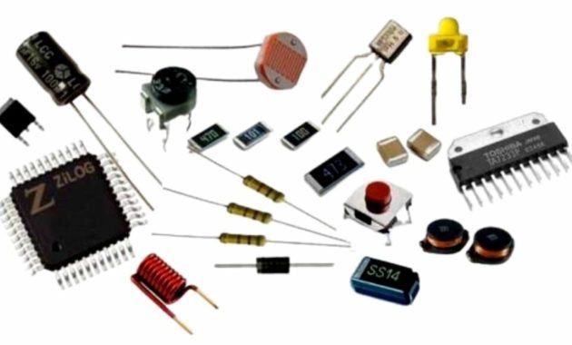
    Any electronic device that is used today turns out to have the smallest components in it. Where each component certainly has its own type and function. More or less that’s the picture of the electrical components.

    Well, the electrical components contained in electronic objects themselves are called circuits. For example, there is a component in a cell phone that is used to capture signals.

    Types of Electrical Components

    For a more complete explanation, here is an explanation of the types of electrical components and their functions that you need to know.

    The types of electrical components that are important for you to know are:

    1. Battery
    2. Transistor
    3. Transformer
    4. Microcontroller
    5. Resistor
    6. Inductor
    7. Capacitor
    8. Switch
    9. Diode

    Electrical circuits are used to conduct conductive electric current in electronic components. Its function is very important, namely so that electronic devices can turn on and function properly. There are two types of components, namely active and passive components.

    While the type and function of the circuit will be discussed in more detail below.

    1. Battery 

    Battery 

    The electrical component of the battery is a component for storing chemical energy which will be converted into electricity in electronic devices.

    You could say this component is very easy to find in electronic devices. For example like in cell phones, radios, watches and so on.

    2. Transistor 

    Transistor 

    The electrical component that is the main component in electronic devices is the transistor . Because one of the components of the transistor will amplify, control, direct, modulator, oscillator and much more for the quality of electricity.

    3. Transformer

    Transformer

    The electrical component of the transformer is one of the electrical components so that the AC voltage can go up and down. This condition will produce very clear sound, images, and so on.

    Examples of its use can be found in household electrical power .

    4. Microcontroller 

    Microcontroller 

    The electrical component of the microcontroller is a component to carry out certain tasks in electronics. Of course it depends on the type of tool itself. Well, the microcontroller is often called an IC or integrated circuit .

    Microcontroller is almost the same as a sensor for measuring electrical quantities in electronics. Where this sensor will process various kinds of information captured through signals.

    5. Resistors

    Resistors

    The electrical component of the resistor has the main function of regulating the electric current in the electronic device so that it is stable and safe.

    This component is also passive and can limit the electric current.

    6. Inductors

    Inductors

    One of the most important electrical components is the inductor. Components that will form coils in electronic devices. The shape of this component is an arrangement of wire turns on top of the circuit.

    7. Capacitor 

    Capacitor 

    A capacitor is a type of electrical component that functions to store current. The time to save it is quite limited. This is because the electrical component of the capacitor has a certain material whose active power is also limited.

    8. Switch

    Switch

    The external electrical components of electronic devices are switches , fuses and button switch buttons. These three components main function is to turn on or break the current in electrical or electronic devices. This component is also used to protect the electrical voltage.

    9. Diode 

    Diode

    The electrical component of the diode is one of the active components in electronic circuits. This component is able to conduct or inhibit electric current from the opposite direction. The materials used are semiconductor materials .

    Conclusion

    Thus a discussion of the meaning of electrical components. Starting from the types of components to examples of electronic devices that contain components, you can see above. Hope it helps you to get to know each component type and its function better, huh?

  • What is Microcontroller

    What is Microcontroller

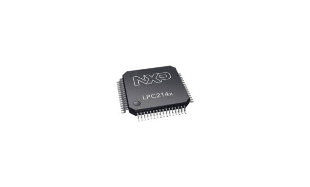
    you certainly don’t know a tool called this microcontroller.

    It can be said that this microcontroller is a chip that has an important role in programming in various electronic devices.

    In this article, we will discuss the understanding of microcontrollers, working principles, structures, block diagrams, advantages, disadvantages, types, functions and differences. For that, see the discussion below.

    What is Microcontroller

    What is Microcontroller

    Microcontroller is a small computer that is packaged in the form of an IC (Integrated Circuit) chip and is designed to perform certain tasks or operations.

    Generally a microcontroller IC consists of one or more processor cores (CPU), memory (RAM and ROM) and programmable input and output devices.

    In its application, the micro controller which in English is called the microcontroller  is used in products or devices that are controlled automatically.

    Examples include car engine control systems, remote controls, medical devices and devices that use other embedded systems.

    The use of this microcontroller is increasingly popular because of its ability to reduce the size and cost of a product or design when compared to designs built using microprocessors with memory and separate input and output devices.

    Microcontroller Working Principle

    Microcontroller Working Principle

    After discussing the meaning of the microcontroller, then the next thing is that there is a working principle.

    Microcontroller is used as a controller or controller of a system. In carrying out these functions, these components require the support of other parts such as those incorporated in the microcontroller IC.

    Depending on the function and purpose, any incoming data or commands are then processed in the CPU section. The processing is assisted by other parts such as timers, RAM, CDA or ADC.

    Difference Between Microcontroller and Microprocessor

    Difference Between Microcontroller and Microprocessor

    Microcontroller is an IC component that performs the controlling function. It contains other components.

    Examples such as ADC, RAM, CDA and many more. The data processing center of the microcontroller is called the CPU.

    While the microprocessor is the CPU (Control Processing Unit) itself, so the history of the microprocessor can be referred to as part of the microcontroller.

    This microprocessor has components such as ALU (Aritmati Logic Unit), registers, control unit and interconnected CPU.

    To better understand how it works, you can see the image of the microprocessor block diagram above.

    Microcontroller Block Diagram and Structure

    Microcontroller Block Diagram and Structure

    The following is the structure and block diagram of the microcontroller along with an explanation of its main parts.

    1. CPU

    CPU is the brain of the microcontroller. The CPU is responsible for fetching instructions (fetch), decoding them (decode), then finally executing (execute).

    The CPU connects every part of the microcontroller into one system. Its main function is to retrieve and decode instructions.

    Instructions taken from program memory must be decoded or decoded by the CPU.

    2. Serial Port (Serial Port)

    The serial port provides various serial interfaces between the microcontroller and other peripherals such as the parallel port.

    3. Memory (Storage)

    This memory is in charge of storing data. The data is data that has been processed (output) or data that has not been processed (input).

    This storage is in the form of RAM and ROM. ROM is used to store data for a long period of time.

    While RAM is used to store data temporarily while the program is running until it is finally moved to ROM.

    As for some parts of RAM, including:

    • Contact point
    • Packaging chips
    • CSP (Chip Scale Package)
    • DIP (Dual In-Line Package)
    • PCB (Printed Circuit Board)
    • TSOP (Thin Small Outline Package)
    • DRAM (Dynamic Random Access Memory)

    4. Parallel Input/Output Port

    Parallel input/output ports are used to drive or connect various devices such as LEDs , LCDs , printers, memory and other input/output devices to the microcontroller.

    5. ADC (Analog to Digital Converter)

    ADC converter (Analog to Digital Converter) is used to convert analog signals to digital form.

    The input signal in this converter must be in analog form (eg output from a sensor) while the output is in digital form.

    Digital outputs can be used for various digital applications such as digital displays in measuring devices.

    6. DAC (Digital to Analog Converter)

    DAC (Digital to Analog Converter) performs the ADC (Analog to Digital Converter) conversion reversal operation.

    The DAC converts the digital signal into an analog format. This DAC is usually used to control analog devices such as DC motors and so on.

    7. Interrupt Control

    Interrupt Control is in charge of controlling delays in microcontroller programming.

    The interrupt control section can be operated internally or externally.

    8. Special Functioning Block

    The special functioning block is an additional part that is made to have a special function.

    Usually this block is found in the microcontroller architecture in robotics machines. Not all devices use this section.

    9. Timer and Counter

    This timer/counter is used for measuring time and counting tools. The existence of this component is very important.

    Because time information is often used to make system settings more accurate and effective.

    Advantages and Disadvantages of Microcontroller

    After the previous admin explained about the definition of a microcontroller, working principles, differences, structure and block diagrams, then there are advantages and disadvantages that you can know.

    The main advantages of the microcontroller:

    • The time required to perform the operation is low.
    • Easily connect additional RAM, ROM and I/O ports.
    • Most pins can be programmed by the user to perform various functions.
    • Can reduce the cost and size of the system, due to complete integration in a microcontroller.
    • The microcontroller acts as a microcomputer without the need for any additional digital components.
    • The use of the microcontroller is simple and easy for troubleshooting and system maintenance.

    Disadvantages of the microcontroller:

    • Most are only used in micro-equipment.
    • Cannot connect with high power devices directly.
    • Microcontrollers have a more complex architecture than microprocessors.
    • Only execute a limited number of times at the same time.

    Microcontroller Types

    Microcontrollers are divided into several types according to their function. The types of microcontrollers include:

    1. AVR Microcontroller

    AVR microcontroller is a type of 8 bit RISC microcontroller. This type is included in the RISC, so all the instruction code will be packaged in a clock cycle.

    AVR is the most common type of microcontroller used in electronics and instrumentation.

    This microcontroller is a type of microcontroller architecture that is the mainstay of Atmel. This architecture is specially designed by offering various advantages and improvements from the existing microcontroller architecture.

    Atmel has produced various series of AVR microcontrollers and has been marketed worldwide as a microcontroller with low cost and high performance characteristics.

    the AVR microcontroller has been widely used, because it offers a very complete range of features, is easy to obtain and has an affordable price.

    2. MSC 51 . Microcontroller

    The MSC 51 type microcontroller is included in the CISC family where almost all instructions will be executed at 12 clock cycles.

    This type of microcontroller uses the Harvard architecture and was originally designed specifically for single-chip microcontroller applications.

    However, the expansion mode allows an external 64 kb ROM and an external 64 kb RAM to be addressed by means of a separate chip selection path for program access and data memory.

    One of the advantages of the 8051 microcontroller is the inclusion of a boolean processing engine which allows bit-level boolean logic operations to be performed efficiently in internal registers and RAM.

    Therefore, MCS51 is often used in early PLC designs. MCS51 is an atmel production which is divided into 2 versions, namely a 20 foot version and a 40 foot version.

    Almost all types of MCS51 microcontrollers are equipped with PEROM flash (Programmable Eraseable Read Only Memory) as program memory media and the arrangement of these IC legs reaches each version.

    3. PIC Microcontroller

    PIC stands for Programmable Interface Controller. But along with its development, it underwent a change into a Programmable Intelligent Computer.

    PIC is a type of RISC type microcontroller where this microcontroller uses the Harvard architecture that has been made by microchip technology.

    It was first developed by the general instrument microelectronic division which has the name PIC1640.

    PIC microcontroller is a single circuit that has a small size and contains memory processing units, clocks and inputs or outputs in a single unit.

    This PIC can be purchased blank which is then added with a certain control program.

    This PIC is very popular among developers and hobbyists, because the cost is fairly cheap.

    Wide availability and use, large application databases and programming via serial port connections that exist on a computer.

    4. ARM . Microcontroller

    The microcontroller is a processor with a 32-bit RISC family of instruction set architecture that has been developed by ARM holdings.

    ARM (Advanced RISC Machine) was previously known as the Acorn RISC Machine.

    Initially, the ARM Processor was developed by PCs or personal computers by Acorn Computers.

    However, with the dominance of the Intel x86 Microsoft process on compatible IBM PCs, Acorn Computer has gone out of business.

    Microcontroller Function

    As for some of the main functions of the microcontroller, including:

    • As a counter
    • As a flip-flop
    • As an oscillation generator
    • As a decoder and encoder
    • As a timer or timer
    • As ADC (Analog to Digital Converter)

    Thus an explanation of the definition of a microcontroller, working principle, structure, block diagram, advantages, disadvantages, types, functions and differences. Hopefully it can be useful for all of us. Bye bye, thank you

  • Integrated Circuit (IC) : Definition, History, Functions, Types and Examples

    Integrated Circuit (IC) : Definition, History, Functions, Types and Examples

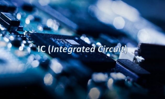
    Do you know what IC is? In general, IC is an important component that we often find in an electronic circuit.

    This time, we will discuss in more detail what IC is. Starting from understanding, history, types, functions, and also examples.

    So, don’t miss the complete information below, okay?

    What is IC / Integrated Circuit ?

    What is IC

    IC stands for Integrated CircuitBriefly, the definition of IC is an active electronic component . Which in it consists of a collection of thousands or even millions of resistors, transistors, diodes and capacitors.

    All of these elements are assembled into one electronic component and then integrated in a small package that we know as an IC.

    In terms of language, this IC is usually referred to as an Integrated Circuit. To make it, you need semiconductor materials in the form of silicon.

    IC serves as a logic gate whose job is to control a circuit. When using IC, the electronic device will have a small or portable form. This is why the appearance can be more concise, practical and more modern.

    history of Integrated Circuit

    IC history

    IC invented by whom?

    IC history was first introduced in 1958. This technology was introduced by a worker from Texas named Jack Killby.

    After being introduced for the first time, six months later IC was re-developed with a more sophisticated format than before.

    Robert Noycer is a person who succeeded in making IC fabrication. Which IC is made with a system connected to a silicon chip.

    With this discovery, IC is known as a popular technology and continues to grow rapidly from time to time.

    This IC is very influential on the appearance of today’s electronic equipment. Just imagine, how big the old electronics were because they still used vacuum tubes as their basic components.

    Now with the IC, almost all electronic equipment today has a thinner and more practical form.

    But not so when IC technology was invented. Some electronic devices have had significant changes.

    As we can see now, electronic equipment such as mobile phones, laptops or televisions have a slimmer and lighter form.

    In addition, IC technology is also proven to be able to make electricity consumption much lower.

    Therefore, nowadays almost every electronic component uses IC technology as its main internal part.

    What is the functions of IC?

    What are the functions of ICs?

    As we discussed above, IC is the main component used for electronic circuits .

    The IC functions for electronic devices are divided into 3 parts, namely:

    1. Linear IC
    2. Digital IC
    3. Mixed IC

    The following is an explanation of the IC functions of the 3 parts above, namely:

    1. Linear IC

    Linear IC

    Linear IC is also known as Integrated Circuit Analog. This linear IC can only operate on a continuous waveform signal.

    Here are some functions of the linear IC that you need to know.

    • Power amplifier (power amplifier).
    • Micro signal amplifier (microwave amplifier)
    • voltage regulator (voltage regulator)
    • RF and IF amplifier (RF And IF amplifier)
    • Multiplier
    • Voltage comparator
    • Radio frequency reception (radio receiver)
    • Operational amplifier
    • Signal booster and so on.

    2. Digital IC

    Digital IC

    igital IC is a type of IC that is popular for its use in the latest electronic equipment. For example, ICs are embedded in calculators, smartphones and laptops.

    These digital ICs generally have input and output voltages. Where each voltage has two levels, namely high and low. As for binary code, generally use the symbols of the numbers 1 and 0.

    The tasks and functions of digital ICs are as follows.

    • As a logic gate.
    • flip-flop
    • Timer
    • Counter
    • multiplexer
    • Memory
    • Calculator
    • Microprocessor and so on.

    3. Mixed IC

    Mixed IC is a type of IC that consists of a combination of analog IC types and digital ICs. The main function of the Mixed IC is to convert from analog signals to digital signals and vice versa.

    As technology develops, mixed ICs are also used for digital signal integration and RF functions.


     the Types of IC

     the Types of IC

    Having previously known about the various functions of IC, then next we will discuss about the types of IC. Let’s look at the explanation of the following IC classification.

    1. Transistor Transistor Logic (TTL)

    Transistor transistor logic (TTL) is a type of digital IC that is quite widely used in electronic circuits. Because the TTL IC has a relatively low voltage source. That is only about 4.75 volts to 5.25 volts.

    TTL ICs are built using transistors as the main element. The function of the transistor in this case is as a logical variation, so it is often referred to as Transistor Logic.

    In TTL ICs, several transistors are combined into one. So that it forms two states, namely on / off or functioning as a switch .

    TTL ICs also have multiple logic gates. Where each gate has a different function. These include AND, NAND, OR, NOR, and XOR. In addition, this component also has several other logical functions.

    For example, such as econder, multiplexer, decoder, and also memory.

    2. IC-CMOS

    2. IC-CMOS

    IC-CMOS stands for complementary with MOSFET. Which, the CMOS IC consists of a combination of MOSFETs. IC-CMOS uses a square wave.

    Where the waves used are generally in two conditions. Namely points 1 and 0 which function as a switch.

    The function of the IC-CMOS is as a logic gate. Where when using it, the electronic circuit can function automatically.

    IC-CMOS can usually function optimally when given an electric current of 12 volts. In this type of IC, there are several functions of logic gates.

    Among them are AND, NAND, OR, NOR, and XOR functions. Then there are also other logic functions such as multiplexer, decoder, econder and memory.

    3. Linear IC

    Linear ICs are not included in the category of digital ICs. This is why linear ICs and digital ICs work differently. If the digital IC usually uses a contact signal, then this linear IC uses a sinusoidal wave.

    The sinusoidal wave contained in the linear IC functions as an amplifier or amplifier. So, the IC does not have a function as a logic gate. Because its main function is specifically designed as a voltage amplifier.

    Linear ICs in general also have a proportional circuit. So, it is balanced in order to produce an output that is proportional to the input value. An example of the application of a linear IC is that it is used as an operational amplifier.


    Advantages and Disadvantages of IC

    IC is an electronic element that has many advantages and benefits. However, in addition to having advantages, these electronic components of course also have disadvantages.

    What are the advantages of using IC and what are the disadvantages? Check out the full review below!

    1. Advantages of IC

    Here are some of the advantages of IC in electronic circuits are:

    • IC has a much larger size.
    • Has a light weight.
    • Can be produced simultaneously or in large quantities so that the selling price can be cheaper.
    • Soldering and interconnecting ICs with very few IC internal components.
    • The use of electrical power can be smaller and of course efficient.
    • Easier to replace and repair if there is damage.
    • Suitable for operating systems with low signal.
    • Can perform complex functions and work systems.

    2. Lack of IC

    In addition to having many advantages, IC also has several disadvantages. Among the disadvantages of IC are :

    • The IC can only be operated on low-voltage systems.
    • IC cannot trigger or generate high power.
    • ICs need to be handled with care as they are very sensitive to Electrostatic Discharge.
    • IC is not resistant to high temperatures. This is why a fan or heatsink is needed to lower the temperature around the IC.
    • Tolerance to voltage is very small and limited.

    Conclusion :

    In short, IC is an electronic component that contains thousands of transistors, diodes and capacitors. Technically the IC functions as a logic gate to control an electronic circuit.

    With the IC technology, electronic devices have a significant improvement. Among them are slimmer, portable and also compact. In addition, the IC also saves electrical energy. So that its use is very popular until now.

    Well, how? Do you understand what IC is? See you on the next material about electricity.