Tag: electricity

  • Electrical Grounding: Functions, Types, How to Install

    Electrical Grounding: Functions, Types, How to Install

    As we know, this ground is also known as grounding. Where this grounding or grounding is a complementary system that is in every electrical installation. Its own function is as a grounding system.

    In addition, the installation of grounding is also useful to provide protection for home electrical installations from various disturbances and hazards. How, interested to know more about Arde?

    In this article, we will thoroughly discuss what is a grounding or grounding system. Starting from the understanding, function, how it works, symbols, to how to install and how to make a simple ground. We will also examine whether grounding can save electricity.

    Definition of Electrical Grounding

    Definition of Electrical Grounding

    When viewed from its function, it can be said that grounding or what is also known as grounding is a grounding system in the form of a separate cable line that does not connect with other electrical wiring installations installed in home electrical installations to the ground point (earth) .

    So this system was created with the aim of eliminating the potential difference that occurs in the electrical circuit . In addition, at the same time aims to release the excess electric charge that arises.

    With the installation of grounding, when there is an excess load on the electrical installation, the charge will automatically flow into the ground.

    Because the soil has a very large mass and volume, if there are disturbances or problems related to electric charge, it will be quickly neutralized. It is for this purpose that a grounding or grounding system is installed.

    Electrical Grounding / Grounding Function

    Judging from its function, of course this Ground or Grounding needs to be installed in every electrical installation, right? Whether it’s for personal needs such as home areas or industrial areas such as factories, of course it requires the presence of Ground as security.

    The function of grounding is as a form of protection. By installing grounding, electrical installations can avoid the following risks:

    • Grounding serves to prevent large electrical leakage. For example, in the event of an electric short circuit, insulation leakage, and avoiding people from being exposed to electric shocks.
    • Prevents in the event of an induction in the flow voltage.
    • Serves as a protector from the threat of static electricity. Especially static electricity that has a voltage with a very high scale such as a lightning strike.
    • Grounding also serves as a reference for measuring the electric current in the installation.
    • Grounding can also prevent damage caused by voltage leakage.
    • Ground also serves to neutralize noise caused by several factors. Among them due to the quality of components that are far from standard or power quality that is not good.

    How Electric Ground Works

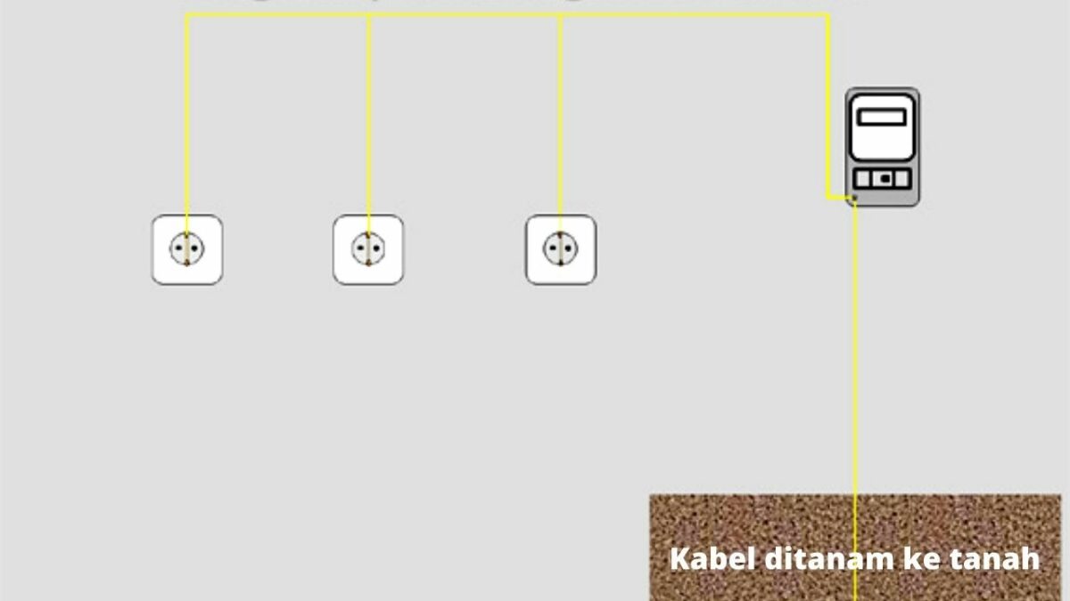
    If observed, the ground installation area is generally deliberately placed close to the kWh meter. So from the kWh meter, the neutral and ground cables are combined together with the phase cable. Then this cable will be connected to the entire network and also the socket.

    From this socket, the grounding will be connected and connected to various electrical equipment . For example, home electrical appliances such as refrigerators, TVs, radios, computers and so on.
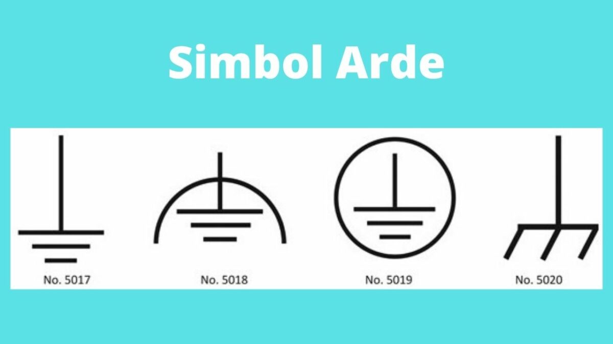
    Grounding symbol

    In general, grounding or ground is denoted by certain symbols. This electrical installation symbol is used when you want to draw an electronic circuit .

    Let’s take a look at some of the most common Ground symbols below. Use the following symbols to explain what the meaning of Grounding is each.

    Grounding symbol

    Various Grounding Systems

    When making electrical installations, of course the security system is the most important thing to pay attention to. Therefore, carrying out a grounding or grounding system is important to do.

    Before discussing further about how to install a grounding cable, of course we need to know the various types. The following is a discussion of various grounding systems that you need to know.

    1. Safety Grounding

    Safety grounding is one system that is often used in grounding installations. Safety grounding is used with the aim of neutralizing the impact of dangerous electric currents.

    For example, if there is a voltage and electric current that goes up or down. Whether it’s caused by an electromagnetic wave whose source of emission comes from a flash of lightning or comes from various other reasons.

    To overcome this, the installation of safety grounding can be an option. Because of this, safety grounding systems are often applied to various electrical lines. It is easy to say that grounding is one of the lightning protection systems.

    2. RF Grounding

    RF grounding is a grounding system whose designation is generally used in communication devices. One example is like radio. As for the process of installing RF grounding , it is mostly applied to devices with large needs.

    The purpose of the installation of this system is to reduce the impact of radiation. Especially to ward off the risk of radiation. As we know, this radiation can arise from the emission of radio communication waves.

    Wire Color For Ground

    Wire Color For Ground

    Before you install a grounding system, of course you also need to know the standard size of the home electrical installation cable. Because this cable is the main component needed to make ground or grounding.

    The wire for grounding is usually green or yellow with a green stripe. Cables with yellow green are generally used for conductors.

    For example, its use for various types of conductors. For example, such as earthing conductors and protective conductors. In addition, this yellow green wire is also used to connect equipotential bonds to the ground.

    Cable Size For Ground

    The ground wire for the grounding system is done by planting a pipe in the ground. Where this pipe will be installed on the terminal part of the socket.

    How to install the grounding on the socket must meet the applicable size standards so that its function can be maximized.

    What you need to know, too, is that the installation method will affect the level of security and also the quality of the ground.

    Therefore, the size and specifications of the cable are also points that should not be ruled out if you want to install grounding at home, right?

    The size of the house electrical cable for grounding can later be adjusted to the standards that have been set. The following is the standard size of the power cord for installing grounding in areas of the house that need attention.

    • The use of wires for grounding generally uses yellow-green wires.
    • Minimum grounding cable diameter using a 50 mm cross-section. But when using a cable with a larger diameter is also allowed.
    • Especially for grounding or grounding in a location that is quite sensitive, try using the HVSC (High Voltage Single Core) cable.
    • For outdoor installations, grounding can use a 50 mm NYA type cable.

    How to Install a Good and Standardized Ground

    how to install the correct ground

    The size of the power cord and its strength do have different specifications. The larger the diameter used for grounding, the better the flow of electric current in the circuit.

    With a good flow of electric current, it will not cause a greater burden. In addition, the waste of electricity can also be avoided. So, if someone asks whether grounding can save electricity?

    So the answer is yes. Logically, this grounding or grounding will make the flow of electricity in each circuit better than before. How, of course interesting if you can save electricity, right? In addition, the security of the installation is also more guaranteed with this Grounding.

    Let’s just look at how to install a good grounding cable and of course according to the standards below:

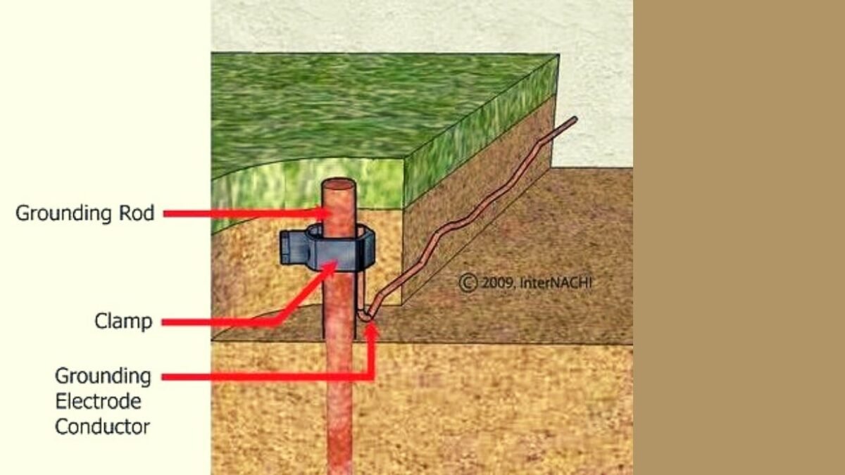
    1. Installing the Grounding Rod

    Installing a grounding or grounding rod is an important step that should not be missed. The more ground rods installed, the better for the installation.

    What are the requirements for installing a grounding rod? Here are the steps that need to be done.

    • Ground rods should be planted with more than one number. Also, make sure to be at least 5 meters apart from each other.
    • Ground rods should be installed more than one and arranged in parallel.
    • Ground rods should be avoided from sandy or rocky soil types because they are poor media.
    • To maximize the grounding system, stick rods should be planted at a distance not too far from the house.

    2. Material Selection For Ground

    To install a good grounding, the material used is also very important to note.

    What are the points to consider when choosing a material for grounding?

    • Choosing a cable that complies with standards is very important. Both in terms of size, color, and type and material.
    • For stick rods, choose ones made of solid copper.
    • Because iron is a material that rusts easily and is not durable. We recommend that the use of iron material for grounding can be avoided.

    3. Planting Grounding Rod

    The way to install the grounding cable is the next stage, namely the process of planting the grounding rod. You will of course need to dig at the location to be grounded or grounded.

    The electrical grounding depth should not be less than 50 cm from the ground level. More fully, here are some steps that you need to do.

    • First of all, dig a hole with a vertical position and with a depth of approximately 50 cm.
    • After that, plug the stick rod into the hole firmly.
    • Pour enough water into the dug hole. It can also be filled with water until the hole is full.
    • Press the rod down, then lift it for a while so that the water can enter and seep into the soil.
    • Next, re-insert the stick rod to the desired depth.

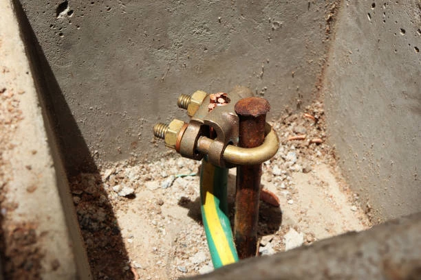
    4. Connecting the Earth to the Cable

    After installing the grounding rod, the next step is to ground the wire. For the process of connecting the ground to the wire, it will be easier if you use the exothermic welding method.

    This exothermic method is carried out by mixing copper material that has previously been melted at high temperatures. Then the copper liquid can be used to permanently join the conductors.

    After the welding is complete, you can clean the surface to be joined from dirt. The goal is to make the connection stronger and not easily separated.

    5. Planting Cable Arde

    The steps for installing the last ground are by planting a ground wire. For this one method, you can apply the following methods:

    • Before embedding the ground wire, you can first measure the grounding resistance. For this purpose, you can take advantage of special tools such as an ohm meter or a grounding tester.
    • After that, dig the soil to the predetermined grounding points.
    • Excavate the track to the grounding terminal with a depth of 40 cm to 50 cm.
    • Next, pull the cable through the path. Make sure the size of the power cord used is of sufficient length.
    • After all the connections are connected, put the marking pipe in that place as a marker.
    • Next, fill the soil with a minimum height of 20 cm.
    • Put a mark on the excavation as a marker that the place has been grounded.

    The Right way to install Ground 

    The Right way to install Ground 

    In order for the grounding installation to function optimally, of course you must follow good and correct installation standards.

    What needs to be considered when installing grounding? Here is the full review.

    • Provide a pipe with a minimum size of 75 cm
    • Planting pipes for grounding should be avoided from places that allow the emergence of puddles when it rains.
    • The distance for the ground pipe and also the kWh meter box should not be too close. For example, in a group with a minimum distance of 180 cm to avoid the kWh meter from being struck by lightning when bad weather occurs.
    • The cross-sectional area of ​​the grounding should be expanded and the conducting depth deepened.
    • The system for new grounding should be made with a parallel system .

    Conclusion

    Grounding or grounding is a grounding system that is often installed in various electrical installations. The main purpose of this grounding is as a means of protecting electrical installations from various problems and disturbances. One of them is from an electric short circuit, lightning strike when it rains and other risks.

    Then, can grounding save electricity? The installation of grounding can also save electricity consumption. With the grounding system, the electrical voltage can be neutralized so that the load is not too much.

    This also affects the obstacles that arise to be reduced. So that automatically the use of electric power will be reduced. So, do you understand the function of grounding in electrical installations?

  • Types of Electrical Components and How They Work: A Comprehensive Review

    Types of Electrical Components and How They Work: A Comprehensive Review

    Any electronic device that is used today turns out to have the smallest components in it. Where each component certainly has its own type and function. More or less that’s the picture of the electrical components.

    Well, the electrical components contained in electronic objects themselves are called circuits. For example, there is a component in a cell phone that is used to capture signals.

    Types of Electrical Components

    For a more complete explanation, here is an explanation of the types of electrical components and their functions that you need to know.

    The types of electrical components that are important for you to know are:

    1. Battery
    2. Transistor
    3. Transformer
    4. Microcontroller
    5. Resistor
    6. Inductor
    7. Capacitor
    8. Switch
    9. Diode

    Electrical circuits are used to conduct conductive electric current in electronic components. Its function is very important, namely so that electronic devices can turn on and function properly. There are two types of components, namely active and passive components.

    While the type and function of the circuit will be discussed in more detail below.

    1. Battery 

    Battery 

    The electrical component of the battery is a component for storing chemical energy which will be converted into electricity in electronic devices.

    You could say this component is very easy to find in electronic devices. For example like in cell phones, radios, watches and so on.

    2. Transistor 

    Transistor 

    The electrical component that is the main component in electronic devices is the transistor . Because one of the components of the transistor will amplify, control, direct, modulator, oscillator and much more for the quality of electricity.

    3. Transformer

    Transformer

    The electrical component of the transformer is one of the electrical components so that the AC voltage can go up and down. This condition will produce very clear sound, images, and so on.

    Examples of its use can be found in household electrical power .

    4. Microcontroller 

    Microcontroller 

    The electrical component of the microcontroller is a component to carry out certain tasks in electronics. Of course it depends on the type of tool itself. Well, the microcontroller is often called an IC or integrated circuit .

    Microcontroller is almost the same as a sensor for measuring electrical quantities in electronics. Where this sensor will process various kinds of information captured through signals.

    5. Resistors

    Resistors

    The electrical component of the resistor has the main function of regulating the electric current in the electronic device so that it is stable and safe.

    This component is also passive and can limit the electric current.

    6. Inductors

    Inductors

    One of the most important electrical components is the inductor. Components that will form coils in electronic devices. The shape of this component is an arrangement of wire turns on top of the circuit.

    7. Capacitor 

    Capacitor 

    A capacitor is a type of electrical component that functions to store current. The time to save it is quite limited. This is because the electrical component of the capacitor has a certain material whose active power is also limited.

    8. Switch

    Switch

    The external electrical components of electronic devices are switches , fuses and button switch buttons. These three components main function is to turn on or break the current in electrical or electronic devices. This component is also used to protect the electrical voltage.

    9. Diode 

    Diode

    The electrical component of the diode is one of the active components in electronic circuits. This component is able to conduct or inhibit electric current from the opposite direction. The materials used are semiconductor materials .

    Conclusion

    Thus a discussion of the meaning of electrical components. Starting from the types of components to examples of electronic devices that contain components, you can see above. Hope it helps you to get to know each component type and its function better, huh?

  • Integrated Circuit (IC) : Definition, History, Functions, Types and Examples

    Integrated Circuit (IC) : Definition, History, Functions, Types and Examples

    Do you know what IC is? In general, IC is an important component that we often find in an electronic circuit.

    This time, we will discuss in more detail what IC is. Starting from understanding, history, types, functions, and also examples.

    So, don’t miss the complete information below, okay?

    What is IC / Integrated Circuit ?

    What is IC

    IC stands for Integrated CircuitBriefly, the definition of IC is an active electronic component . Which in it consists of a collection of thousands or even millions of resistors, transistors, diodes and capacitors.

    All of these elements are assembled into one electronic component and then integrated in a small package that we know as an IC.

    In terms of language, this IC is usually referred to as an Integrated Circuit. To make it, you need semiconductor materials in the form of silicon.

    IC serves as a logic gate whose job is to control a circuit. When using IC, the electronic device will have a small or portable form. This is why the appearance can be more concise, practical and more modern.

    history of Integrated Circuit

    IC history

    IC invented by whom?

    IC history was first introduced in 1958. This technology was introduced by a worker from Texas named Jack Killby.

    After being introduced for the first time, six months later IC was re-developed with a more sophisticated format than before.

    Robert Noycer is a person who succeeded in making IC fabrication. Which IC is made with a system connected to a silicon chip.

    With this discovery, IC is known as a popular technology and continues to grow rapidly from time to time.

    This IC is very influential on the appearance of today’s electronic equipment. Just imagine, how big the old electronics were because they still used vacuum tubes as their basic components.

    Now with the IC, almost all electronic equipment today has a thinner and more practical form.

    But not so when IC technology was invented. Some electronic devices have had significant changes.

    As we can see now, electronic equipment such as mobile phones, laptops or televisions have a slimmer and lighter form.

    In addition, IC technology is also proven to be able to make electricity consumption much lower.

    Therefore, nowadays almost every electronic component uses IC technology as its main internal part.

    What is the functions of IC?

    What are the functions of ICs?

    As we discussed above, IC is the main component used for electronic circuits .

    The IC functions for electronic devices are divided into 3 parts, namely:

    1. Linear IC
    2. Digital IC
    3. Mixed IC

    The following is an explanation of the IC functions of the 3 parts above, namely:

    1. Linear IC

    Linear IC

    Linear IC is also known as Integrated Circuit Analog. This linear IC can only operate on a continuous waveform signal.

    Here are some functions of the linear IC that you need to know.

    • Power amplifier (power amplifier).
    • Micro signal amplifier (microwave amplifier)
    • voltage regulator (voltage regulator)
    • RF and IF amplifier (RF And IF amplifier)
    • Multiplier
    • Voltage comparator
    • Radio frequency reception (radio receiver)
    • Operational amplifier
    • Signal booster and so on.

    2. Digital IC

    Digital IC

    igital IC is a type of IC that is popular for its use in the latest electronic equipment. For example, ICs are embedded in calculators, smartphones and laptops.

    These digital ICs generally have input and output voltages. Where each voltage has two levels, namely high and low. As for binary code, generally use the symbols of the numbers 1 and 0.

    The tasks and functions of digital ICs are as follows.

    • As a logic gate.
    • flip-flop
    • Timer
    • Counter
    • multiplexer
    • Memory
    • Calculator
    • Microprocessor and so on.

    3. Mixed IC

    Mixed IC is a type of IC that consists of a combination of analog IC types and digital ICs. The main function of the Mixed IC is to convert from analog signals to digital signals and vice versa.

    As technology develops, mixed ICs are also used for digital signal integration and RF functions.


     the Types of IC

     the Types of IC

    Having previously known about the various functions of IC, then next we will discuss about the types of IC. Let’s look at the explanation of the following IC classification.

    1. Transistor Transistor Logic (TTL)

    Transistor transistor logic (TTL) is a type of digital IC that is quite widely used in electronic circuits. Because the TTL IC has a relatively low voltage source. That is only about 4.75 volts to 5.25 volts.

    TTL ICs are built using transistors as the main element. The function of the transistor in this case is as a logical variation, so it is often referred to as Transistor Logic.

    In TTL ICs, several transistors are combined into one. So that it forms two states, namely on / off or functioning as a switch .

    TTL ICs also have multiple logic gates. Where each gate has a different function. These include AND, NAND, OR, NOR, and XOR. In addition, this component also has several other logical functions.

    For example, such as econder, multiplexer, decoder, and also memory.

    2. IC-CMOS

    2. IC-CMOS

    IC-CMOS stands for complementary with MOSFET. Which, the CMOS IC consists of a combination of MOSFETs. IC-CMOS uses a square wave.

    Where the waves used are generally in two conditions. Namely points 1 and 0 which function as a switch.

    The function of the IC-CMOS is as a logic gate. Where when using it, the electronic circuit can function automatically.

    IC-CMOS can usually function optimally when given an electric current of 12 volts. In this type of IC, there are several functions of logic gates.

    Among them are AND, NAND, OR, NOR, and XOR functions. Then there are also other logic functions such as multiplexer, decoder, econder and memory.

    3. Linear IC

    Linear ICs are not included in the category of digital ICs. This is why linear ICs and digital ICs work differently. If the digital IC usually uses a contact signal, then this linear IC uses a sinusoidal wave.

    The sinusoidal wave contained in the linear IC functions as an amplifier or amplifier. So, the IC does not have a function as a logic gate. Because its main function is specifically designed as a voltage amplifier.

    Linear ICs in general also have a proportional circuit. So, it is balanced in order to produce an output that is proportional to the input value. An example of the application of a linear IC is that it is used as an operational amplifier.


    Advantages and Disadvantages of IC

    IC is an electronic element that has many advantages and benefits. However, in addition to having advantages, these electronic components of course also have disadvantages.

    What are the advantages of using IC and what are the disadvantages? Check out the full review below!

    1. Advantages of IC

    Here are some of the advantages of IC in electronic circuits are:

    • IC has a much larger size.
    • Has a light weight.
    • Can be produced simultaneously or in large quantities so that the selling price can be cheaper.
    • Soldering and interconnecting ICs with very few IC internal components.
    • The use of electrical power can be smaller and of course efficient.
    • Easier to replace and repair if there is damage.
    • Suitable for operating systems with low signal.
    • Can perform complex functions and work systems.

    2. Lack of IC

    In addition to having many advantages, IC also has several disadvantages. Among the disadvantages of IC are :

    • The IC can only be operated on low-voltage systems.
    • IC cannot trigger or generate high power.
    • ICs need to be handled with care as they are very sensitive to Electrostatic Discharge.
    • IC is not resistant to high temperatures. This is why a fan or heatsink is needed to lower the temperature around the IC.
    • Tolerance to voltage is very small and limited.

    Conclusion :

    In short, IC is an electronic component that contains thousands of transistors, diodes and capacitors. Technically the IC functions as a logic gate to control an electronic circuit.

    With the IC technology, electronic devices have a significant improvement. Among them are slimmer, portable and also compact. In addition, the IC also saves electrical energy. So that its use is very popular until now.

    Well, how? Do you understand what IC is? See you on the next material about electricity.

  • How Induction Stoves Work

    How Induction Stoves Work

    How Induction Stoves Work, Superior and Safe Electric Stoves. Induction cookers heat cooking utensils placed on them directly by magnetic induction. Cooking utensils do not get hot because the surface of the stove is hot like on a gas stove. But the heat is directly flowed into the cooking utensil which makes the food in it cooked. So, the surface of the stove is not hot, it is safe to touch.

    Induction Stove Components and Their Functions

    There are several main components in an electric stove. These components also have their respective roles. Are as follows :

    1. thermostat

    The function of this component is to regulate the temperature of the electric stove. With this component can be determined how high the desired heat temperature when cooking.

    2. Control Knob

    This component is useful for disconnecting the electric stove from the power source. The form of a button can be a touch screen or a regular button.

    3. Timer

    The advantage of electric stoves is the presence of a digital timer. From this component, you can set a warning for the length of time required to warm up.

    4. Halogen Coil/Lamp

    A coil is a kind of wire that is able to convert electric current into heat. The mechanism of action uses the principle of electromagnetic induction. While the halogen lamp uses the principle of heat radiation.

    5. Fuse

    Induction hobs use a series of fuses to protect the heating element. This fuse will blow if too much electricity flows through it. Its main function is to prevent spikes from reaching the heating element.

    How Induction Cookers Work

    The working principle of the induction cooker can be explained as follows

    1. When the stove is connected to a regular power source with a frequency of 50 Hz. Using the converter and controlling element, the mains frequency of 50 Hz is converted into a high frequency of up to 25 kHz (the frequency can be adjusted via the controlling element).
    2. This high-frequency electricity is supplied to the induction coil, then current flows through the coil. Keep in mind here that the current flowing into the induction coil is alternating current with high frequency.
    3. This alternating current generates magnetic field lines. This magnetic field always changes according to changes in the current, namely ac.
    4. This magnetic field cuts the cooking place (container) made of metal (conductor). What happens when metal is cut by a magnetic field that changes all the time?
    5. In metal, there will be an induced emf (voltage) ( Faraday’s law ).
    6. Because the metal for cooking is a single unit, it is electrically the same as being short- circuited. What happens when the voltage is short-circuited? There will be a current which in this case is rotating in direction. Because of its direction, this current is then called an eddy current or eddy current .
    7. The eddy current that flows in the metal and the metal still contains a resistance even though it is small, so heat arises and this heat is used for cooking.

    The heat generated by the stove depends on the electrical energy converted to heat. The power of the stove will be determined by the frequency of the electricity supplied to the induction coil. The higher the frequency, the higher the power of the stove and the higher the temperature (heat) of the stove.

    How it Works Induction stoves do not produce fire, there is no risk of exploding if the gas cylinder is not installed properly like on a gas stove. The surface of the induction cooker is also not heated, so it is safe to touch.

    The Kanahome induction stove is equipped with a sensor to stop the heating process if the temperature on the surface of the stove is too hot or if no cooking utensils are placed on the stove, there is also a timer feature so that the stove will turn itself off within the set time.

    The heat generated by induction stoves is more efficient than gas stoves. The flat shape makes the heat received by the cookware more evenly and 90% accepted by the cookware. While the gas stove produces uneven fire, sometimes the fire is large in certain parts so that the heat is only on a certain side, the heat received by the cooking utensils is only 65-70%. Therefore, cooking with an induction cooker is also faster and more efficient. In addition, the bottom of your pan will not turn black from being exposed to excessive heat.

  • How Geothermal Power Plant Work System

    How Geothermal Power Plant Work System

    What exactly is a Geothermal Power Plant?
    Geothermal Power Plant is a power plant that uses geothermal energy as its energy source.
    Geothermal energy is one of the natural resources in the form of hot water or steam which is formed through natural heating.
    The word geothermal  comes from the Greek “geo” which means earth and “therme” which means heat. In other words, geothermal energy refers to the energy produced by heat stored in the earth’s core. As a source of energy that comes directly from nature and is renewable in nature, its use does not have a negative impact on the environment and humans.
    Indonesia is very fortunate to be blessed with abundant geothermal resources because of the many volcanoes in Indonesia.

    Things that need attention in choosing technology for using geothermal energy to be converted into electrical energy are:

    1. Temperature; geothermal fluids with a high temperature of> 225 oC have long been used for electricity generation. Medium temperature 150 – 225 oC
    2. Resource reserves of up to 25-30 years
    3. Steam Quality; It is expected that the pH is almost neutral, because if the pH is very low the corrosion rate of the material will be faster.
    4. Well Depth and Chemical Content Usually not very deep (no more than 3 km). The location is relatively easy to reach.
    5. The likelihood of a hydrothermal eruption is relatively low. The production of hot fluid from the bowels of the earth can increase the risk of hydrothermal eruptions.

    Geological Characteristics of Geothermal Areas

    1. Heat Source: Magma which has a temperature of ~ 700 C
    2. Bed Rock: The bedrock layer which is the hard rock of the lower layer
    3. Aquifer (Permeable Zone Layer): is a layer that can be flowed by water. This layer serves as a reservoir
    4. Cap Rock: A layer of hard rock as a cover rock layer.
    5. Water Replishment: as water enhancer.
    6. Surface Manifestation, namely: Symptoms that appear on the earth’s surface (craters, hot springs, geysers, volcanoes, etc.).

    Benefits of Geothermal Energy

    The benefits of geothermal energy obtained from the center of the earth is one of the environmentally friendly alternative energies.
    The way to take advantage of geothermal energy is to drill the part that is the location of geothermal energy to release steam at a certain depth.
    In modern times, geothermal energy is not only used as electricity generation, it turns out that energy from geothermal can also be used as other means such as to help plant growth or other agricultural products that are in the greenhouse during winter. Even this energy can also be used as a space heater and guard the road or sidewalk so that it is not too slippery.
    In the future geothermal energy will be of great help to us in many ways. However, we also have to know that not all regions have locations that have the potential to be used as a source of geothermal energy. With the increasing need for energy in modern times, there are many benefits that we get by taking advantage of geothermal energy.

    How Geothermal Power Plants Work

    How does Geothermal Power Plant work?
    For more details on how the PLTP works, let’s look at the picture and description below.

    1. Steam is supplied from production wells through a steam transmission system which then enters the Steam Receiving Header as a steam collecting medium. The Steam Receiving Header is equipped with a Rupture Disc which functions as the last safety unit. If there is over pressure in the Steam Receiving, the steam will be discharged through the Vent Structure. The Vent Structure functions for warming-up in the pipe line when starting the unit and as a safety valve that will relieve pressure if a sudden trip occurs.

    2. From the Steam Receiving Header, the steam is then flowed to a Separator (Cyclone Type) which functions to separate steam (pure steam) from foreign objects such as heavy particles (Sodium, Potassium, Calcium, Silica, Boron, Ammonia, Fluor etc.).

    3. Then the steam enters the Demister which functions to separate the moisture contained in the steam, so it is hoped that clean steam will enter the turbine.

    4. The steam enters the turbine so that the energy conversion occurs from the heat energy contained in the steam into kinetic energy which is received by the turbine blades. The turbine which is coupled with the generator will cause the generator to rotate when the turbine rotates so that there is a conversion from kinetic energy to mechanical energy.

    5. The rotating generator produces Electricity

    6. Exhaust Steam from the Turbine is condensed in the Condenser with a Jet Spray system (Direct Contact Condensor).

    7. NCG (Non Condensable Gas) which enters the Condenser is sucked by the First Ejector then enters the Intercondensor as a cooling medium and NCG catcher. After from the Intercondensor, NCG is sucked again by the Second Ejector into the Aftercondensor as a cooling medium and then discharged into the atmosphere through the Cooling Tower.

    8. From the condenser, the water from the condensation is flowed by the Main Cooling Water Pump into the Cooling Tower. Furthermore, the cooling water from the cooling tower, dry steam, is recirculated back into the condenser as a cooling medium.

    9. The Primary Cooling System besides being a cooler the Secondary Cooling System also fills the cooling water to the Intercondensor and Aftercondensor.

    10. The overflow from the Cold Basin Cooling Tower will be accommodated for the benefit of the Reinjection Pump.

    11. River Make-Up Pump operates only when filling the Basin Cooling Tower.

    Advantages And Disadvantages of Geothermal Power Plants

    Advantage

    There are actually many advantages to geothermal power. Here are the advantages of geothermal power:
    1. First and foremost, geothermal energy is renewable energy, which means that as long as we don’t pump too much water the energy will continue to exist.
    2. Geothermal energy does not produce pollution, and at the same time, does not contribute to the greenhouse effect.
    3. The location of the power plant for geothermal energy does not require a large area and therefore tends to have little impact on the surrounding environment.
    4. Since geothermal energy is energy that comes from within and from itself, no sources outside of fuel are required to keep the generator running.


    Deficiency

    Although it has many benefits, there are still some disadvantages of geothermal energy. These deficiencies can affect or all three stages of production – pre-production, production and post-production:
    1. Perhaps the biggest drawback of geothermal power is that you don’t build a geothermal power plant anywhere you want. You will need an exact location containing hot rock. After that, not all of these rocks can be drilled because they are too hard. These rocks must also have a depth that allows them to be drilled.
    2. There are also other risks to consider – sometimes a geothermal site may be drilled but has run out of steam. It could be that this happens when the dry season lasts for a long time.
    3. The final loss concerns the potential hazards of geothermal energy. When it is carried out into the soil and which can be mined, this could also mean that there is a possibility that other substances that are not environmentally friendly could also be involved. Harmful gases and minerals can seep from underground and it is very difficult to find ways to safely dispose of these substances into the surrounding environment.
    However, there are certainly advantages and disadvantages caused by exploration. However, with increasingly sophisticated technology, these losses can be anticipated and minimized.
    Why is PLTP now prioritized in Indonesia? Because the profit aspect is greater and Indonesia has abundant geothermal wealth.
  • Michael Faraday

    Michael Faraday

    Michael Faraday (1791-1867), was a physicist and chemist from England. His well-known discoveries are electromagnetic induction and the laws of electrolysis. Faraday’s initial research was in chemistry, under the guidance of Sir Humphry Davy and found two types of carbon chloride and benzene. In his research, Faraday also succeeded in liquefying several types of gases.

    Michael Faraday is an expert in chemistry and physics. He was born on September 22, 1791 and died on August 25, 1867. He is known as a pioneer in researching electricity and magnetism, even many scientists say that he is the greatest researcher of all time. Some of the concepts he derived directly from experiments, such as lines of magnetic force, have become ideas in modern physics.

    Faraday was born in a poor family in Newington, Surrey near London. Young Faraday was a critical child, but he received little education compared to primary school. Even so, it did not make him feel inferior and give up hope to continue learning. When he was 14 years old, he was apprenticed in a bookbinding business. This is where he got interested in physics and chemistry. After hearing the lecture of a famous chemistry lecturer at the time, Humphry Davy, he sent his lecture notes to the lecturer. It turned out that the lecturer was interested and appointed Faraday as his assistant at the famous University Laboratory in London, when he was 21 years old.

    In his first year of work in the laboratory, Faraday discovered two chlorocarbons and succeeded in liquefying chlorine gas and several other gases. Then managed to separate benzene compounds in 1825 where he was appointed chairman of the laboratory.

    In 1807, Davy, who had a great influence on Faraday’s thought, had predicted that the metal sodium and potassium could be precipitated from their compounds by means of an electric current, a process known as electrolysis. Faraday passionately tried hard to prove his professor’s prediction and in 1834 it became a reality, a new law on electricity emerged, known as Faraday’s Law.

    Faraday’s research into electricity and electrolysis was guided by his belief that electricity is one of the other forces of nature such as heat, light, magnetism and chemical tendencies. Although his idea was wrong, this made him enter the electromagnetic world.

    In 1821, Faraday investigated the magnetic field around a conductor that was energized by an electric current which was first discovered by Hans Christian Oersted in 1819. In 1831 Faraday discovered electromagnetic induction and showed the emergence of an induced current in a coil due to an electric current in another coil. . At the same time, Faraday also conducted successful research in the field of electrolysis.

    The thought and one experiment of electromagnetic phenomena that Faraday demonstrated regarding the concept of lines of force were refuted by most of the European mathematical physicists, they assumed that electric charges attracted and repelled each other by distance and made the lines of force insignificant. However, a well-known physicist at the time, James Clerk Maxwell accepted Faraday’s thoughts and converted them to mathematical equations and became the cornerstone of the birth of modern field theory.

    Another result of Faraday’s creativity (1845) was about the intensity of a magnetic field that could rotate a polarized light field and is now known as the Faraday effect. This phenomenon has been used to determine molecular structures and provide information about the magnetic fields of galaxies.

    Faraday describes much of his research on electricity and electromagnets in three volumes entitled Experimental Researches in Electricity (1839, 1844, and 1855). His research notes are dated in Experimental Researches in Chemistry and Physics (1858). In 1855, Faraday stopped researching because of health problems but he continued his work as a lecturer until 1861. On August 25, 1867, Faraday the inventor died leaving all his work, but all his services, both products and thoughts, will always be remembered by the world and make him the true inventor.

    Michael Faraday’s work 

    1. 27 Oct 1813 With Humphrey Davy investigating his theory of volcanic activity.
    2. 1821 Describes the dynamo principle.
    3. 1821 Invented the first electric motor.
    4. 1821 Examining the magnetic field around conductors.
    5. 1823 Melts chlorine gas.
    6. 1831 Discovering electromagnetic induction.
    7. 1831 Research on moving magnets causes electric currents.
    8. 1831 Finding lines of magnetic force.
    9. 1831 Invented the electric dynamo.
    10. 1831 Inventing electric transformers.
    11. 1831 Making laws about induction.
    12. 1832 Explaining the laws of electrolysis and taking the term “ion” for the particles believed to be responsible for carrying current.
    13. 1833 Developed his laws in the field of electrolysis.
    14. 1845 Investigating the rotation of light polarized by magnetic fields.
    15. 1845 Discovered that the propagation of light in matter can be affected by external magnetic fields.
    16. 1850 Corrects his failed research to find a relationship between gravity and electromagnetic fields.

    25 August 1867 Michael Faraday died in England as a chemist and physicist who contributed to the advancement of science

  • Europe Wants To Build Solar Power Plants In Space

    Europe Wants To Build Solar Power Plants In Space

    power plant solar power is already being built on Earth. But the European Space Agency ( ESA ) will make it in space . What is the goal?

    ESA said that the development of solar power plants in outer space is a response to climate change on Earth which continues to be a big challenge.

    Increasing global temperatures to erratic weather patterns have forced humans to change the way they produce and consume energy.

    Renewable energy technology can be the answer, but it has problems in energy absorption that is not constant, as reported by IFL Science .

    On Earth, new energy can be obtained when the wind blows and the sun is shining, while humans need electricity all the time.

    The most likely way to work around this is to produce solar energy from a place that is always reached by light, namely in outer space.

    This option has many advantages. Space-based solar power plants can orbit facing the Sun in 24 hours.

    The Earth’s atmosphere also absorbs and reflects some of the Sun’s light, so solar cells above the atmosphere will receive more sunlight and produce more energy.

    But one of the main challenges that must be overcome is how to assemble, launch and implement such large structures.

    A solar power plant should probably have an area of ​​10 square kilometers or the equivalent of 1,400 football fields. Designers should use lightweight materials, given that the biggest cost lies in launching into space on a rocket.

    One proposed solution is to develop thousands of smaller satellites that will be bundled together and configured to form one large solar generator.

    Earlier in 2017, scientists at the California Institute of Technology outlined a design for a modular power plant, which consists of thousands of tiles of ultralight solar cells. The team of experts also demonstrated a prototype tile weighing only 280 grams per square meter.

    Reporting from IFL Science on Saturday (12/12/2020), another big challenge is getting the power sent back to Earth.

    Scientists plan to convert electricity from solar cells into energy waves and use electromagnetic fields to transfer it to antennas on Earth’s surface.

    The antenna will convert the waves back into electricity. Previously, a team of scientists led by the Japan Aerospace Exploration Agency had developed designs and demonstrated an orbiter system that could do this.

    While much work remains to be done in this area, scientists hope solar power generation in outer space will soon become a reality in the coming decades.

    Scientists in China have designed a system called Omega which is targeted to be operational by 2050. The system is expected to be able to supply 2GW of power to Earth’s grid.

    In comparison, to get that much power with solar panels on Earth would require more than six million solar panels.

    That’s the plan of a European space bandan who wants to build a solar power plant in outer space.

  • 6 Engineers Who Revolutionized the World’s Electrical System

    6 Engineers Who Revolutionized the World’s Electrical System

    All the technology that you use today, will not function without electricity . The study and development of electricity was long before the first industrial revolution began.

    Here are 6 engineers who are pioneers in the world electrical system revolution.

    1. Michael Faraday

    Michael Faraday

    In 1831, Faraday discovered the phenomenon of electromagnetic induction. The results of his experiments are now the basis of modern electronic technology.

    2. Alessandro Volta

    In 1800, Volta published the electronic device “voltaic pile” which became the forerunner of battery technology

    3. Georg Ohm

    Ohm showed that the electric current flowing in a conductor is proportional to the voltage and inversely proportional to the resistance.

    His name is immortalized as the unit for electrical resistance.

    4. Andre-Marie Ampere

    Andre-Marie Ampere

    Ampere conducted a theoretical and practical study of electric currents. Because of his services, his name is immortalized as a unit of electric current.

    5. Gustav Kirchoff

    German physicist who studied the characteristics of electric currents in conductors.

    His famous contribution is Kirchhoff’s Law, where the amount of current entering the branch is equal to the amount of current flowing out.

    6. Nikola Tesla 

    Tesla was the engineer who made the AC power system widely used today.

    Contributions include AC electric motors, electricity distribution, and many others.

    Thus the discussion about the six engineers who revolutionized the world’s electrical system. Hopefully useful and inspire us all.