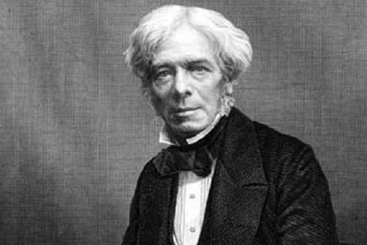
A capacitor or capacitor by Michael Faraday (1791-1867) is essentially a device that can store energy/electrical charge in an electric field, by accumulating an internal imbalance of electric charge or an electrical component capable of storing an electric charge formed by a surface. (disk or chip) connected which are separated by an insulator.
Michael Faraday
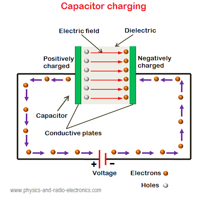
When a capacitor is connected to a voltage source, the disk or plate is filled with electrons. When electrons separate from one plate to another, the electron charge will exist between the two plates. This charge is caused by a positive charge on the plate that loses electrons and a negative charge on the plate that gains electrons.
Capacitors are electronic components that have the ability to store electrons for a certain time or electronic components that are used to store electric charges consisting of two conductors and are separated by an insulating material (dielectric material) each conductor is called a chip.
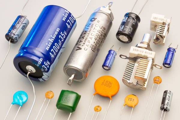
Like resistors, capacitors are one of the passive components that are widely used in making electronic circuits. Capacitors differ from accumulators in that they store electric charge, especially when there is no chemical change in the capacitor material. Another definition of a capacitor is an electronic component that can store and release an electric charge. Capacitors or often called capacitors are electrical components that are made in such a way that they are able to store an electric charge.
The principle of a capacitor in general is the same as a resistor which is also included in the passive component group, namely the type of component that works without the need for bias current. Capacitors consist of two conductors (metal plates) separated by an insulating material (insulator). This insulating insulator is often referred to as a dielectric material.
The dielectric substance used to block the two transmitters of the component can be used to distinguish the type of capacitor. Some definitions of capacitors that use dielectric materials include paper, mica, liquid plastic and others.
If both ends of the metal plate are given an electric voltage, then positive charges will collect on one of the metal legs (electrodes) and at the same time negative charges will accumulate on the other metal end. Positive charges cannot flow towards the negative end of the pole and conversely negative charges cannot go to the positive end of the pole, because they are separated by a non-conductive dielectric material.
This electric charge is “stored” as long as there is no conduction at the ends of the legs. The ability to store electric charge in a capacitor is called capacitance or capacity. Capacitance is defined as the ability of a capacitor to accommodate electron charges. Coulombs in the 18th century calculated that 1 coulomb = 6.25 x 10¹⁸ electrons.
Then Michael Faraday postulated that a capacitor will have a capacitance of 1 farad if with a voltage of 1 volt it can carry a charge of 1 coulomb of electrons. With the formula it can be written: Q = CV Where: Q = electron charge in C (coulombs) C = capacitance value in F (farads) V = voltage in V (volts) In the practice of making capacitors,
The capacitance is calculated by knowing the area of the metal plate (A), the distance (t) between the two metal plates (dielectric thickness) and the dielectric constant (k) of the material. The formula can be written as follows: C = (8.85 x 10⁻¹²) (k A/t) The following is a table of examples of the constant (k) of some simplified dielectric materials Vacuum air k = 1 Aluminum oxide k = 8 Ceramics k = 100 – 1000 Glass k = 8 Polyethylene k = 3
As the ability of a capacitor to accommodate the charge of electrons. Coulombs in the 18th century calculated that 1 coulomb = 6.25 x 10¹⁸ electrons. Then Michael Faraday postulated that a capacitor will have a capacitance of 1 farad if with a voltage of 1 volt it can carry a charge of 1 coulomb of electrons.
With the formula it can be written:
Q = CV
With assumption :
Q = electron charge C (Coulomb)
C = capacitance value in F (Farad)
V = high voltage in V (Volts)
In the practice of making capacitors, the capacitance is calculated by knowing the area of the metal plate (A), the distance (t) between the two metal plates (dielectric thickness) and the dielectric constant (k) of the material. With the formula can be written as follows:
The way a capacitor works in a circuit is to flow electrons into the capacitor. When the capacitor is filled with electrons, the voltage will change. Furthermore, electrons will exit a capacitor and flow into the circuit that needs it. That way, the capacitor will generate a reactive circuit.
But we do not deny, even though a capacitor component has a different shape and size, the function of a capacitor is still very much needed in an electronic component or even an electronic circuit.
As for the two plates or plates in a capacitor separated by an insulator, basically no electrons can cross the gap between the two plates. When the battery is not connected, the two pieces will be neutral (uncharged). When the battery is connected, the point where the wire at the negative end of the pole is connected will repel electrons,
while the point where the positive pole is connected attracts electrons. The electrons will be scattered throughout the capacitor plates. Momentarily, electrons flow into the right-hand plate and electrons flow out of the left-hand plate; in this condition current flows through the capacitor even though there are no electrons flowing through the gap between the two plates.
After the outside of the chip is charged, it will gradually reject the new charge from the battery. Therefore the current in the plates will decrease in magnitude with time until both plates are at the voltage that the battery has. The plate on the right will have an excess of electrons which is measured with a charge of -Q and on the plate on the left it is charged with +Q .
How is a capacitor made?
If two or more plates are facing each other and are limited by insulation, then the plate is electrified, a capacitor will be formed (the insulation that limits the two plates is called a dielectric).
The dielectric materials used are different, so the naming of capacitors is based on the dielectric material. The area of the plate opposite the dielectric material and the distance between the two plates affect the capacitance value.
In a circuit that does not occur stray capacitors. Such a property is called parasitic capacitance.The cause is the presence of adjacent components in adjacent electrical conductor lines and adjacent coils of wire. The picture above shows that there are two plates that are bounded by air. The distance between the two plates is expressed as d and the input voltage.
Capacitance
The capacity of a capacitor is the ratio of the amount of electric charge to the voltage across the capacitor. C = Q / V If calculated by the formula C = 0.0885 D/d. Then the capacity in units of pico farads D = the area of the plates facing each other and influencing each other in cm2. d = distance between plates in cm. If the voltage between the plates is 1 volt and the magnitude of the electric charge on the plates is 1 coulomb, then the ability to store electricity is called 1 farad. In reality capacitors are made with units below 1 farad. Most electrolytic capacitors are manufactured from 1 microfarad to several millifarads.
Capacitor Formula
The Capacitor Formula consists of several formulas that are used to calculate the amount of electric charge both generated by the capacitor and the incoming electric charge. The following are some formulas about capacitors with parallel circuits, series circuits and series and parallel capacitor circuits whose units of calculation are farads (F). The following are the formulas that are stored in the pieces of an electrically charged capacitor as follows:
Here is an Example of the Capacitor Formula Rumus
Explanation:
Q = Charge in Coulombs
C = Capacity in Farads
V = Voltage in Volts
(1 Coulomb = 6.3*1018 electrons)
The capacitor can function as a battery because the voltage remains in the capacitor even though it is not connected, the length of the remaining voltage depends on the capacity of the capacitor itself. Examples of other formulas in a capacitor circuit:
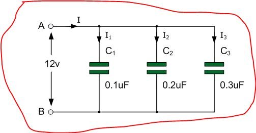
Formula for Capacitors with Parallel Circuit
C Total = C1 + C2 + C3
In the Capacitor Formula above it can be concluded that, in the parallel capacitor circuit there is no division for voltage or electric charge at all, all voltages will have the same amount at every point in the parallel capacitor circuit the reason is because at the same point the parallel capacitor is connected , so it has no significant changes.
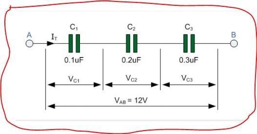
Formula for Capacitors with Series Circuit
1/C Total = 1/C1 + 1/C2 + 1/C3
In the formula for a capacitor with a series circuit above, it can be concluded that, at each measurement of this series capacitor, there is a voltage distribution from the voltage source to each point, which in the end when combined by adding up the voltages from each point it will look the same as the sum of the voltages. from the voltage source.
Series and Parallel Capacitor Formulas
C Total = (C1 + C2) // C3
1/CA = 1/C1 + 1/C2 (tie)
In the Capacitor Formula with series and parallel circuits above, it can be concluded that this type of circuit can be calculated by combining several equations that can be seen from the two capacitor formulas, namely series and parallel. So we can find out the total number of combinations between these 2 types of capacitors.
Capacitor circuit is divided into two, namely series circuit and parallel circuit. The calculation method is almost the same as for series and parallel circuits on resistors. The following is the equation of the capacitor circuit.
Series circuit
The series circuit on a capacitor is a capacitor circuit by connecting the NOT similar poles between the capacitors, as shown in the following figure:
The replacement capacity in a series circuit is:
1 C tot = 1 C 1 + 1 C 2 + 1 C 3 Q tot = Q 1 = Q 2 = Q 3 V tot = V 1+ V 2+ V 3
The series arrangement of capacitors is that the capacitors are arranged in one unbranched connecting line. If a capacitor is arranged in series, the total replacement capacitor can be determined from all the capacitors in the series circuit. In this series arrangement the following rules apply:
The charge on each capacitor is equal to the sum of the charges on the replacement capacitor.
Q s = Q 1 = Q 2 = Q 3 = Q 4
The potential difference (V) across the ends of the replacement capacitor is equal to the potential difference across each capacitor
Vs = V1 + V2 + V3 + V4
The capacity of the replacement capacitor can be found by the formula
Cs = 1/C 1 + 1/C 2 + 1/C 3 + 1/C 4
For n capacitors with the same capacity, you can use the quick formula
Cs = C/n
What needs to be remembered because the replacement capacity of the series arrangement of several capacitors is always smaller than their respective capacity, so capacitors arranged in series can be used to reduce the capacity of a capacitor.
Parallel Circuit
Parallel circuit is a series of capacitors by connecting the SAME poles between the capacitors, as shown in the following figure:
The replacement capacity in a parallel circuit is:
C tot = C 1+ C 2+ C 3 Q tot = Q 1+ Q 2+ Q 3 V tot = V 1 = V 2 = V 3
The charge on the replacement capacitors is equal to the sum of the individual capacitors (same as the voltage in a series circuit)
Qp= Q1 + Q2 + Q3 + Q4 + dst…
The potential difference of each capacitor is equal to the potential difference of the original source (same as the charge in a series circuit)
Вп = В 1 + В 2 + В 3 + В 4
The capacitance of the replacement capacitor in a parallel circuit is equal to the sum of the total capacitances of the capacitors in the circuit.
Cp = C1 + C2 + C3 + C4
Because the replacement capacity of all parallel circuits is always greater than that of each capacitor in the circuit, so parallel arrangement can be used to increase the capacity of the capacitor.
Combined Series and Parallel
This arrangement is a combination of series and parallel arrangement. The formula that applies is the same as the formula that applies to the two previous types of circuits. Here, my friend must be shrewd in identifying from a series of combinations which are series and which are parallel. The following is a simple example of a combined circuit
Capacitor Energy
An electric charge creates an electric potential and work is required to move it. To charge a capacitor requires electrical work, and this electrical work is stored in the capacitor as energy. The loading starts from zero to Q coulomb. The energy equation for the capacitor can be written as:
According to the type, capacitors can be divided into 2 types, namely:
Fixed capacitor
Fixed capacitor is a capacitor whose capacitance value cannot be changed and the value has been set by the manufacturer. The shape and size of the capacitor still vary and differ from one another depending on the material of manufacture.
Fixed capacitors are also divided into 2, namely:
Polar capacitor
1) Electrolytic capacitor
This capacitor is a type of polar capacitor or has 2 poles on the legs. The long leg is the positive pole and the short leg or the leg that has a special sign is the negative leg. The installation of electrolytic capacitors in electronic circuits should not be reversed, especially for DC current circuits but for AC current it is not a problem.
This capacitor should not be exposed to excessive heat during the soldering process because the electrolyte contained in the capacitor can boil and cause the capacitor to be damaged. The following is a picture of an electrolytic capacitor. These capacitors are available with a large enough capacity, the smallest having a capacity of 0.1 microFarrad and the largest commonly available on the market is 47000 microFarrad. But the author has encountered this capacitor in the size of 1 Farrad at a price that is enough to make the bag dry. The working voltage of this capacitor is very diverse but is usually written on the capacitor body. Its working voltage ranges from 6.7 V to 200 Volts.
2) Tantalum capacitor
In accordance with technological developments in the field of electronics, electronic component manufacturers are always creating new inventions in the form of capacitor components that have high reliability. In general, these capacitors are made with a small physical shape and are red or green in color. Because they have high reliability, tantalum capacitors are quite expensive.
Non-polar capacitor
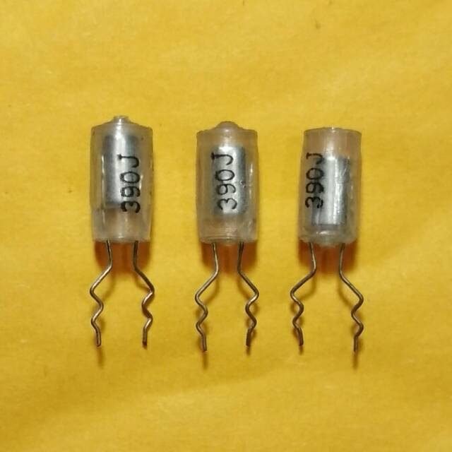
1) Ceramic capacitor
Named ceramic capacitors, because these capacitors are made of ceramic dielectric material. Ceramic capacitors come in various shapes and sizes. This capacitor is stable enough that it is often used in electronic circuits. The capacitance value of this capacitor is usually written in color code, but there are also those that are written directly on the body using numbers.
2) Polyester capacitor
The role of plastic is not limited to making bags or household appliances, but also plays a role in the manufacture of electronic components, namely capacitors. Plastic capacitors are very popular in their use and in the field of electronics known as polyester capacitors. In general, these capacitors are made with a small and flat shape. This capacitor does not have a polarity so the installation will not be difficult. The inclusion of the capacitance is usually in color code.
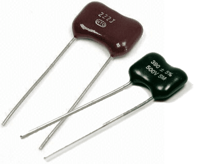
3) Mica capacitor
Mica capacitors are components that were born since the first generation and are still widely used today because of their high reliability in addition to having stable properties and low tolerance. As the name implies, this capacitor is made of mica. The use of this type of capacitor is in circuits associated with high frequencies. The capacitance of this capacitor is 50 to 10,000 F
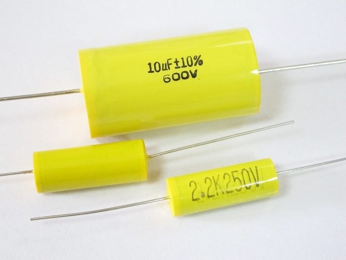
4) Film capacitor
Film capacitors, the dielectric is made of film. The amount of capacitance is listed with a color coded in the form of a bracelet and the reading method is almost the same as reading the resistor color code.
5) Paper capacitor
It is called a paper capacitor because the dielectric material is made of paper. This type of capacitor has been born since the first generation where at that time still using a vacuum tube. This type of capacitor is now rare and almost not used anymore. In the installation of this capacitor will not be a problem because it is not equipped with polarity. The capacitance of this type of capacitor is 100 pF to 6800 pF.
Capacitor is not fixed (Variable)
A variable capacitor is a capacitor whose capacitance value can be adjusted as needed. The types of variable capacitors are;
Variable capacitor (Varco)
Variable capacitors are a type of capacitor that are larger than fixed capacitors. In accordance with its physical form, the variable capacitor has a large capacitance. Capacitors of this type were made in the first generation. Variable capacitors are widely used in large circuits. The capacity of this type of capacitor usually ranges from 1 F to 500 F.
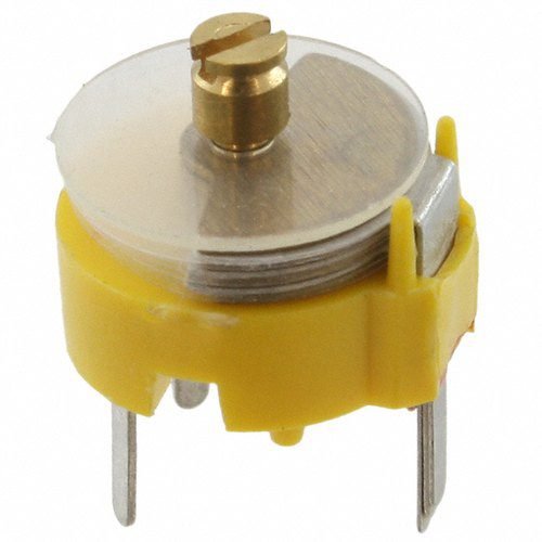
Trimer Capacitor
The trimer capacitor is a variable capacitor that has been developed from the previous variable capacitor which has a small size, so because it has a small size this capacitor is very suitable to be installed in today’s modern circuits.
Trimmer capacitors are equipped with presets, which are tools used to adjust the amount of capacitance. The adjustment can be done using a screwdriver. This type of variable capacitor uses a dielectric material, namely mica or plastic. The capacitance of this type of capacitor is 5 to 30 F
Active capacitor or CDS
Technological developments in the field of electronics are currently growing rapidly so that now many components are appearing that are getting smaller but have better functions than before.
Likewise with capacitor components, currently active types of capacitors have been developed, meaning that these capacitor components will actively flow charge when exposed to light, either sunlight or other light sources. These components are widely used as sensors in garden lighting circuits or alarm circuits or functions as an automatic switch.
Capacitor Function
Capacitor function is needed in an electronic component. Capacitors are electronic components that function to store electric charge, besides that capacitors can also be used as frequency filters. The capacity to store the ability of a capacitor in an electric charge is called Farad (F) while the symbol for a capacitor is C (capacitor).
The function of the capacitor itself is divided into 2 groups, namely capacitors that have a fixed capacity and capacitors that have a capacity that can be changed or in other words variable capacitors. The basic nature of a capacitor is that it can store an electric charge, and for DC current the capacitor functions as an insulator / retainer of electric current, while for AC current the capacitor functions as a conductor / passes electric current.
In its application the capacitor is used as a filter, DC voltage leveler which is used to change the AC voltage to DC, AC wave generator or oscillator and so on, and can also function as impedance (resistance whose value depends on the given frequency), to save power. electricity in fluorescent lamps.
The function of a capacitor in an electronic circuit is as a coupling, a filter in a power supply circuit, a phase shifter, a frequency generator in an oscillator circuit and is also used to prevent sparks in a switch.
To temporarily store current and voltage
As a filter or filter in an electronic circuit such as a power supply or adapter
To eliminate the bounce (sparks) when installed on the switch
As a coupling between one electronic network and another electronic network
To save electricity when installed in fluorescent lamps
As an insulator or electric current barrier for DC or direct current
As a conductor or conduct electric current for AC or alternating current
To even out the DC voltage waveform in the AC to DC voltage converter circuit (adapter)
As an oscillator or AC wave generator (alternating) and so on
Examples Types of Capacitors
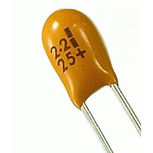
Tantalum Capacitor
Tantalum Capacitor Is a type of electrolytic capacitor whose electrodes are made of tantalum material . This component has a polarity, how to distinguish it by looking for the + sign on the body of the capacitor, this sign indicates that the pin underneath has a positive polarity. It is expected to be careful in the installation of components because they should not be upside down. The temperature and frequency characteristics are better than electrolytic capacitors made of aluminum.
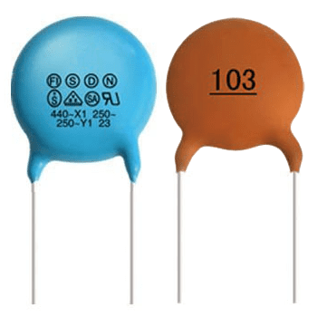
Ceramic Capacitor
The capacitor uses titanium acid barium for its dielectric. Because it is not constructed like a coil, this component can be used in high frequency circuits. The frequency response characteristics need to be taken into account, especially if the capacitor operates at high frequencies.
For frequency response calculations, the unit of quality factor Q ( quality factor ) is also known which is nothing but 1/DF. Usually used to pass high frequency signals to ground . This capacitor is not good for analog circuits, because it can change the shape of the signal. This type has no polarity and is only available with very small capacitor values.
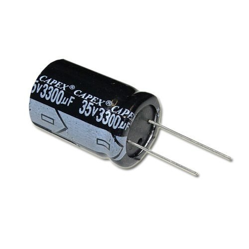
Electrolytic Capacitor
The electrolytic capacitor group consists of capacitors whose dielectric material is a metal-oxide layer. The electrode of this capacitor is made of aluminum which uses a thin oxidation membrane. Generally, capacitors belonging to this group are polar capacitors with + and – signs on their bodies. From these characteristics, the user must be careful in its installation in the circuit, do not turn it upside down. If the polarity is reversed it will be damaged and even “explode”.
To get a large surface, this Aluminum plate material is usually rolled radially. So that way can be obtained capacitors with large capacitance. Usually this type of capacitor is used in power supply circuits , low pass filters , and timer circuits.
This capacitor cannot be used in high frequency circuits. Usually the working voltage of the capacitor is calculated by multiplying the power supply voltage by 2. For example, the capacitor will be supplied with a power supply of 5 volts, meaning the selected capacitor must have a minimum working voltage of 2 x 5 = 10 volts.
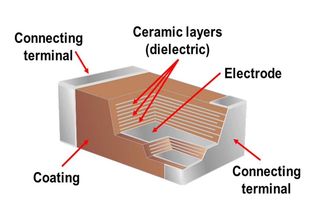
Multilayer Ceramic Capacitor
The material for this capacitor is the same as the type of ceramic capacitor, the difference is in the number of layers that make up the dielectric. In this type the dielectric is arranged in many layers or usually called a layer with a thickness of 10 to 20 m and the electrode plate is made of pure metal.
Besides being small in size and having better temperature characteristics than ceramic capacitors, this type is usually good for applications or passing high frequencies to ground.
Polyester Film Capacitor
The dielectric in this capacitor is made of polyester film . Has better temperature characteristics than all the above types of capacitors. Can be used for high frequency. Usually this type is used for circuits that use high frequencies, and analog circuits. These capacitors are usually called mylars and have a tolerance of ±5% to ±10%.
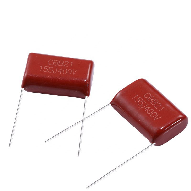
Polypropylene Capacitor
The capacitor in addition has a higher tolerance value than the polyester film capacitor . In general, the capacitance value of this component will not change if it is designed in a system if the frequency through it is less than or equal to 100kHz.
The picture above shows a polypropylene capacitor with a tolerance of ±1%. This type of capacitor is still under development to get a large but small and light capacitance, for example for electric car applications.
Mica Capacitor
This type uses mica as its dielectric material. Mica capacitors have a high level of stability, because of their low temperature coefficient. Because the frequency characteristics are very good, usually these capacitors are used for resonant circuits, filters for high frequencies and circuits that use high voltages, for example: radio transmitters that use transistor tubes. Mica capacitors do not have a high capacitance value, and the price is also relatively high.
Polystyrene Film Capacitor
The dielectric of this capacitor is polystyrene film . This type can not be used for applications that use high frequencies, because the construction is the same as an electrolytic capacitor, which is like a coil. These capacitors are good for timer and filter applications that use frequencies of several hundred kHz.
This component has 2 colors for the electrodes, namely: red and gray. For the red one, the electrode is made of copper, while the gray one is made of aluminum foil.
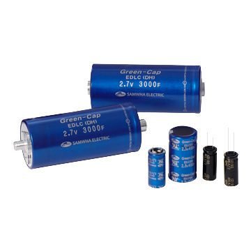
Electric Double Capacitor (Super Capacitor)
This type of capacitor has the same dielectric material as an electrolytic capacitor. However, the difference is that the size of the capacitor is larger than the electrolytic capacitor described above. Usually have units of F. These capacitors have a large voltage limit.
Because it has a voltage limit and a larger shape than other capacitors, this capacitor is also called a super capacitor. The picture of the physical form can be seen above, in Figure 2.13 the capacitor has a size of 0.47F. These capacitors are usually used for power supply circuits .
Trimmer Capacitor
This type of capacitor uses ceramic or plastic as its dielectric material. The value of the capacitor can be changed by turning the screw above it. In the playback is expected to use a special screwdriver, so as not to cause the effect of capacitance between the screwdriver and hand
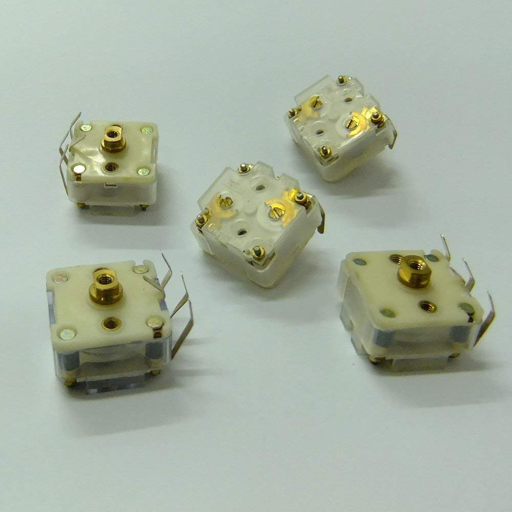
Tuning Capacitor
These capacitors in Japan are referred to as “Varicons”, usually a lot of use as a selector on radio waves. The dielectric type uses air. The capacitance value can be changed by turning the handle on the capacitor body to the right or to the left.